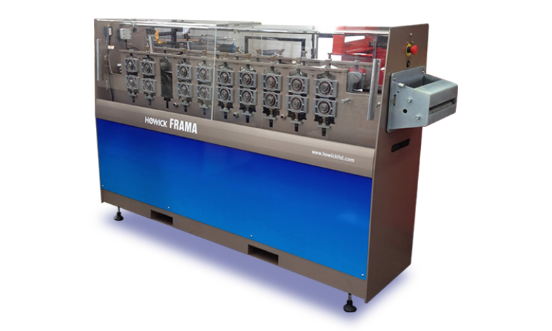
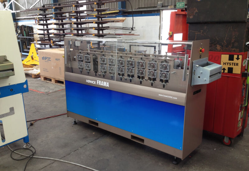
TH200 Tophat Batten
- Gauge Range
-
- Production Speed
-
- Dimensions L x W x H
-
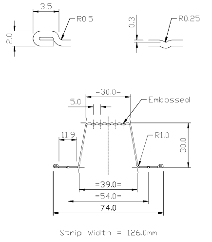
The TH200 produces a tophat batten up to 0.75mm (24 gauge) thickness. The profile has been specially developed for material efficiency with a screw location groove and a rolled safety edge.
All hardware is CE and UL compliant and tested to comply with current CE emissions standards.
- One of the main advantages of using steel battens is that they are dimensionally accurate and stable. This means that you can achieve a higher quality finish in lined walls and ceilings without the need to return to site to repair any, once the building has settled
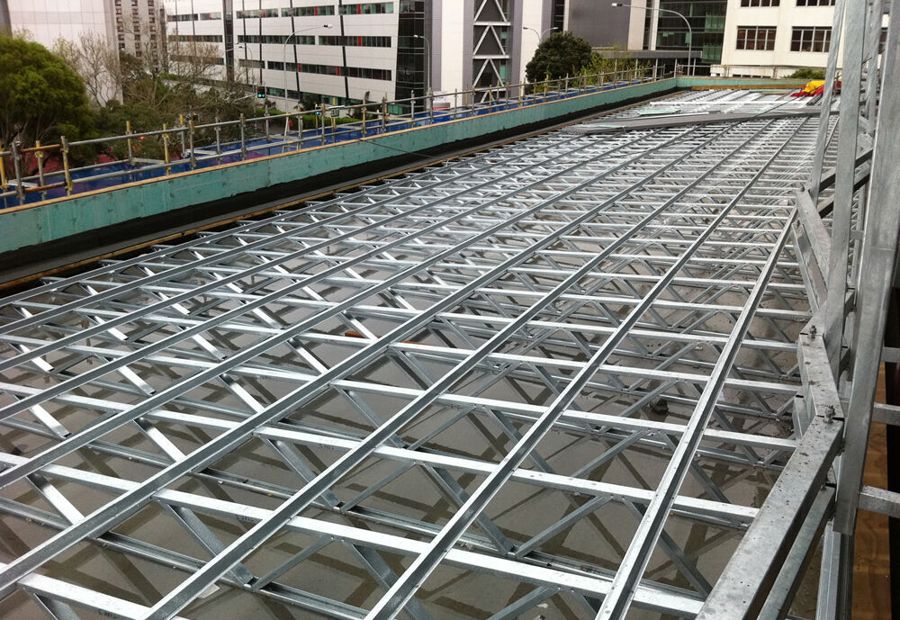
- Tophat roof battens nest together for easy transportation negating movement cracks
- Cut to length reduces wastage and site cutting
- The FRAMA machine control allows for room and building lots to be loaded using our CSV format
- Batch marking is possible with the optional inkjet printer
- Spans up to 900mm at 900mm spacing or 1200mm at 370mm spacing
- Can be used in extra high wind and in snow load situations
- Lightweight 0.836 KG per metre
- Dimensionally stable, battens expand and contract at 0.1% the same rate as the roof in extreme temperature changes
- Steel battens don’t absorb moisture
- No more buckling ridge line flashings
- Battens can be fitted to both timber and steel trusses or rafters.
- 100% recyclable
| TH 200 | ||
| Material Range | 0.75mm | 24 Gauge |
| Product Size | 30mm x 30mm Ceiling Batten | |
| Product Rate | 1500m/hour | 4900 feet/hour |
| Control | FRAMA machine control | |
| Length | 1900mm | 6'2" |
| Width | 500mm | 1'8" |
| Height | 1260mm | 4'2" |
| Weight | 1125kg | 2475lb |
| Electrical Req. | 400 - 460V | 50 - 60Hz |
| Motor Power | 4.0kW | 5.4hp |
| Hydraulic Power | 1.1kW | 1.5hp |
| Hydraulic Tank | 5 litres | 1.3 gal |
| Cover | Fully Guarded with Emergency Stop Buttons | |
| Decoiler | ||
| 1.5T Decoiler | 3300lb Decoiler | |
| Dimensions L X W X H | 1.05m x 1.2m x 1.68m | 3.4' x 6.6' x 5.5' |
| Weight | 350kg | 770lb |
| Drive Motor | 2.2kW | 3hp |
| Jaws | 3 Jaw Self Centring | |
| Jaw Expansion | Hydraulic | |
| Jaw Expansion Range | 480mm - 520mm | 1' 7'' - 1' 8 1/2'' |
| Speed Control | Dancer Arm with Inclinometer | |
| Auto pause at coil end | ||
| Max Coil Weight | 1500kg | 3300lb |
| Max Coil Width | 200mm | 8'' |
| Mac Coil OD | 1500mm | 59'' |
| Nominal Bore | 508mm | 20'' |
| Safety | CE, UL, Cat 3 Compliant | |
|
* Production Speed will vary due to component complexity. Howick Ltd Reserve the right to update the machine specification without notice. |
||
Ceiling Battens
| 30x74x0.55 Top Hat Section Refer: AS/NZS1170 Loadings code also NZS3604:2011 Design to AS/NZS4600 Light Gauge Steel using G250 grade steel |
Ceilings with 0.5kPa Live load Table of max span vs spacings Figs based on max deflection L/500 Connect with min 2 - 10 gauge screws for centres noted |
|||||
|
|
Section Spacings (mm) |
|||||
| Connect with min 2-10 gauge screws for spans as noted | 400 | 400 | 450 | 450 | 600 | 600 |
| Connect with min 1-10 gauge screw for up to 1.0m span | Span (m) | Max Point Load (kN) | Span (m) | Max Point Load (kN) | Span (m) | Max Point Load (kN) |
| Max distributed loads kN/m | 0.200 | 0.225 | 0.300 | |||
| Using 10mm gib ceilings | 1.7 | 0.25 | 1.5 | 0.33 | 1.4 | 0.35 |
| Using 13mm gib ceilings | 1.5 | 0.33 | 1.4 | 0.35 | 1.3 | 0.38 |
| Using 16mm gib ceilings | 1.4 | 0.35 | 1.4 | 0.35 | 1.2 | 0.41 |
| Using 20mm gib ceilings | 1.3 | 0.38 | 1.3 | 0.38 | 1.2 | 0.41 |
CEILING BATTENS
| 30x74x0.75 Top Hat Section Ceilings with 0.5kPa Live load Figs based on max deflection L/500 |
Table of max span vs spacings. Connect with min 2 - 10 gauge screws for centres noted | |||||
|
|
Section Spacings (mm) |
|||||
| Connect with min 2-10 gauge screws for spans as noted | 400 | 450 | 600 | |||
| Connect with min 1-10 gauge screw for up to 1.0m span | Span (m) | Max Point Load (kN) | Span (m) | Max Point Load (kN) | Span (m) | Max Point Load (kN) |
| Max distributed loads kN/m | 0.200 | 0.225 | 0.300 | |||
| Using 10mm gib ceilings | 1.8 | 0.60 | 1.7 | 0.65 | 1.5 | 0.75 |
| Using 13mm gib ceilings | 1.7 | 0.65 | 1.6 | 0.70 | 1.5 | 0.75 |
| Using 16mm gib ceilings | 1.6 | 0.70 | 1.5 | 0.75 | 1.4 | 0.80 |
| Using 20mm gib ceilings | 1.5 | 0.75 | 1.4 | 0.80 | 1.3 | 0.86 |
Battens for Roof and Wall claddings
| 30x74x0.75 Top Hat Section Propriatary steel roofings with wind loads Or 0.25 LL whichever worst case |
Table of max span vs spacings. Pressure Factor Cp = + or - 0.9 | |||||
|
|
Section Spacings (mm) |
|||||
| For connections to wood substrate refer NZS3604:2011 for wind loadings. For connections to min 0.75 ga steel | 600 | 600 | 900 | 900 | 1200 | 1200 |
| Connect with min 1 - 10 gauge screw for up to 0.50kN/m, 2 per 1.0kN/m, 3 per 1.5kN/m, and 4 per 2.0kN/m | Max Span (m) | Max UDL (kN/m) | Max Span (m) | Max UDL (kN/m) | Max Span (m) | Max UDL (kN/m) |
| Medium wind 37m/s | 1.2 | 0.44 | 1.1 | 0.66 | 1.0 | 0.88 |
| High wind 44m/s | 1.2 | 0.63 | 1.0 | 0.95 | 0.9 | 1.26 |
| Very high wind 50m/s | 1.1 | 0.81 | 0.9 | 1.22 | 0.8 | 1.62 |
| Extra high wind 55m/s | 1.0 | 0.98 | 0.9 | 1.47 | 0.8 | 1.96 |
Note: All fixing types are determined as required for the higher uplift loads at the periphery of the roof (based on local pressure factors in AS/NZS 1170.2)

